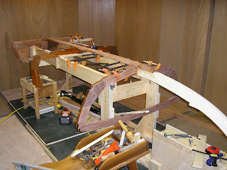
The process of beveling and smoothing all the surfaces that the plywood "skin" mates to is called fairing. It is inherently a bit confusing to the new boat builder as its hard to know where to start, what tools to use, and how much material to remove.
The picture shows the tools I ended up using from top to bottom in the picture: 1) power 3 1/4" hand planer, 2) small belt sander Porter-Cable 2 1/2"X 14", 3) 1" Stanley hand plane, 4) 8" Jack plane, 5) Rasp, 6) Disston Abrader, 7) Long sander (made from 1/4" scrap wood to fit a 3x21 belt from a belt sander).
After filing some notches at the frames to set the angle of the longitudinal pieces, the major wood removal starts to blend the shapes from one spot to the next along the longitudinal pieces. I found the power planer a bit aggressive and hard to see what was happening until after a pass was made. The hand planes turned out to be quite effective at removing material quickly on the curved surfaces. They were a pleasure to use since they are quiet and they allow the surface to be seen as you work which is reassuring . The small Porter-Cable power sander was a great tool as the vacuum pick-up removed the dust effectively and it was fairly easy to see what was being removed. It was great for putting the contour on the frames.

The bottom piece on the right side of this picture is called the shear. It has not been faired yet and is still a square section. The idea is to angle it so the outer surface points towards the member above it (the chine). The trick is that the angle is constantly changing and it turned out that my chine surface was not sufficiently angled to have a prayer of getting a piece of plywood to lay on it and the shear at the same time. So the chine had a couple more laminations of material added to get the bottom angled out enough to "point" towards the shear below it.
In this picture, the bottom piece (shear) is faired so that its surface points toward the chine above. This area of the boat probably took the most time as quite a bit of wood needed to be removed. You can see a lot of plane shavings and dust on the floor.
I think Im done with fairing, but it seems to be a task that could be done to infinity because with every new look it appears that a surface could be sweetened a little more. I think its good enough to move on and Ill fix something if I see the need as I prepare the plywood planking pieces.


 I decided to make templates from the plans for most of the parts in the frames. Using the carbon paper, lines were traced onto material to make the templates. The actual frame pieces were then rough cut, stacked together with double backed tape, the templates double-back taped to the pieces and a trimming router bit with guide bearing used to cut multiple pieces at the same time. In the corners where 1/4" plywood gussets were used, 4 indenticle parts were made at the same time.